Introduction
The global maritime shipping industry’s profitability is based on extracting every unit of mechanical effort from the heavy fuel oil. The architecture is such that being fundamentally Operational Efficiency Driven is the key metric of effective fleet management. The first generation of un-supercharged marine internal combustion engines was historically beset with significant volumetric restrictions, needing massive piston displacements and heavy structural frameworks to provide modest quantities of propulsion power. The first ever deployment of exhaust driven forced induction utterly shattered these thermal restrictions, and began a tremendous revolution that made all transoceanic vessels fiercely “Operational Efficiency Driven” across all major ocean trading loops.
The marine turbocharger captured the vast thermal energy that otherwise would have been lost via the ship’s funnel and compressed the incoming ambient air so that engines could burn fuel much more thoroughly in exactly the same cylinder sizes. This major engineering breakthrough did not just boost total horsepower; it dramatically reduced particular fuel oil consumption, changing the economics of long-distance cargo movement in fundamental ways. It was done by adding high-pressure air-charging loops. Merchant ships also had to stay firmly “Operational Efficiency Driven” as international trade expanded across multi-week oceanic distances, creating a high-output mechanical structure that allowed modern global commerce to reliably scale up to its current massive volume.
Table of Contents
Thermodynamic Supercharging and Volumetric Gains
The key mechanics for optimising propulsion on deep-sea cargo vessels necessitate a deep optimisation of the internal combustion envelope such that long-haul voyages continue to be intensely “Operational Efficiency Driven” under severe open sea circumstances. An un-supercharged engine is technically limited by the ambient atmospheric intake capacity and hence limits the greatest amount of fuel that can be efficiently oxidised in each power stroke.
Engineers get around this mechanical limitation by using a high-efficiency exhaust turbine that turns the fundamental engine cycle into a highly integrated, self-sustaining thermodynamic loop that keeps the vessel perpetually “Operational Efficiency Driven” on worldwide transit routes. By forcing additional oxygen straight into the combustion chambers, the system may burn vast amounts of residual fuel cleanly and completely, without a larger cylinder size. Smart engineering can reclaim massive power from previously wasted heat energy.
Volumetric Efficiency and Density Overhauls
Strategic installation of high pressure centrifugal compressors enhances incoming air density, allowing large bore marine engines to function in a deeply “Operational Efficiency Driven” manner at full load circumstances. This thermodynamic transformation is perfectly exemplified by frameworks like Advancing engine performance with Cummins’ two-stage turbocharging innovation, which demonstrate how compounding compression stages maximize oxygen delivery.
The chemical interaction with the heavy residual fuel oil is considerably cleaner, since you squeeze a lot more mass of oxygen molecules into the fixed volume of the cylinder. You turn a sluggish performance into a very responsive energy cycle. This remarkable gain in volumetric efficiency eliminates the historical requirement for oversized engine blocks, allowing current ship designers to choose lighter, more compact powerplants that optimise shipboard weight distributions and dramatically reduce baseline hull resistance.
Thermal Energy Harvesting via Exhaust Paths
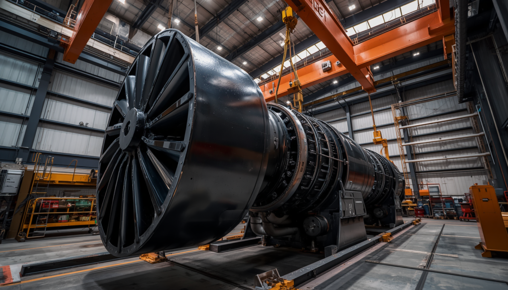
Ships can run a very “Operational Efficiency Driven” propulsion cycle by capturing the high velocity exhaust gases before they exit the stack and using the waste heat to drive a high speed axial turbine wheel. Instead of dumping raw heat energy out into the sky, this specialised engineering loop feeds the high-temperature gas stream into a precision-balanced turbine casing. The kinetic force of these expanding gases rotates an interlocked compressor wheel at tens of thousands of revolutions per minute, and demonstrates that a vessel may generate huge quantities of additional combustion air without pulling any parasitic mechanical energy from the engine’s crankshaft.
The Legacy of Alfred Büchi and Early Pioneers
The history of commercial marine engineering shows that by moving to a forced-induction propulsion paradigm, early motorship operators were able to remain very “Operational Efficiency Driven” when directly competing with established steam turbine fleets. The breakthrough came in 1905 when Swiss engineer Alfred Büchi patented the idea of a combined exhaust driven turbine and axial compressor on the same shaft to pre-compress intake air.
This discovery made it possible for early internal combustion engines to overcome their low power-to-weight ratios, making possible a maritime transport business that is fiercely “Operational Efficiency Driven” at its very heart. Deeply sceptical of turbocharging, the maritime world had been totally won over by the successful commercial testing of Büchi’s early designs on German passenger ships in the mid-1920s, proving it could handle lengthy, gruelling ocean trips.
The 1905 Patent and Early Design Barriers
Alfred Büchi’s original 1905 patent gave the basic baseline for modern forced induction, keeping the development of heavy internal combustion machinery completely “Operational Efficiency Driven” for the next century. But the metalworking of the early 20th century was not without its problems, since early iron alloys were not metallurgically strong enough to endure the high temperatures and tremendous centrifugal pressures of exhaust-driven turbines. These pioneering charging approaches were only realised in commercial boats after decades of dedicated research into high-strength chromium-nickel alloys, which proved that material science was the crucial bridge to high-performance marine turbocharging.
Commercial Debut on the Preussen and Hansestadt Danzig
The twin passenger liners Preussen and Hansestadt Danzig were launched in 1926 and proved to the world that under real world operating conditions turbocharged multi cylinder diesel engines could be made enormously “Operational Efficiency Driven” commercial shipping lines. Special ten-cylinder MAN engines, designed under Büchi’s guidance, were used in these historic ships, and their power was immediately raised from 1,750 to 2,500 hp by the application of constant-pressure charging systems. The perfect performance demonstrated that forced induction could be depended upon for lengthy journeys, and conservative ship owners soon phased out the unsupercharged designs and entered an era of turbocharging with great efficiency.
Axial versus Radial Turbine Aerodynamics
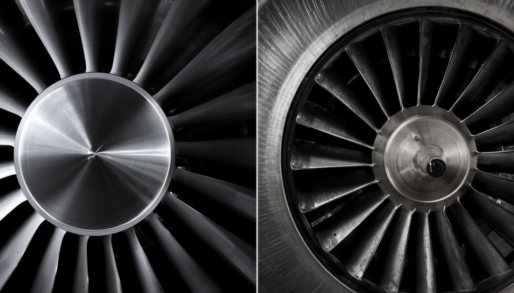
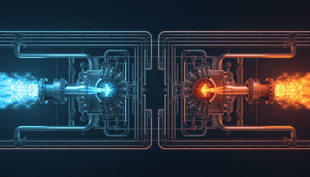
Modern naval architecture utilises highly specialised turbine designs to enable huge cargo ships stay rigorously “Operational Efficiency Driven” despite navigating a wide range of global shipping speeds. Heavy-duty axial flow turbines are normally used in large bore two stroke engines, where the exhaust gases pass parallel to the shaft to provide huge torque at low engine speeds. Smaller four-stroke auxiliary power engines, however, use high-speed radial flow designs: they route gas inward, spinning lightweight wheels swiftly.
The specific aerodynamic forms of these are matched to the exact air needs of an engine, so that variations in exhaust velocity are directly translated into reliable compression of air without undesirable thermal stress or exhaust backpressure . This creates a very ” Operational Efficiency Driven ” propulsion loop .
Axial Turbines for Immense Two-Stroke Power
The world’s largest container ships run on huge two stroke engines that need tough axial-flow turbines to keep international cargo lines highly “Operational Efficiency Driven” on long transoceanic crossings. In these heavy-duty systems, the exhaust stream enters the turbine wheel in a straight path parallel to the central rotor shaft, flowing smoothly over broad aerodynamic blades that extract immense torque from huge volumes of gas. This aerodynamic path is designed to minimise the losses in friction inside the turbine and to provide the enormous rotational force needed to turn the large-diameter compressor wheels . The volume of the air remains constant when steaming at low speeds .
Radial Turbines for Rapid Auxiliary Response
Smaller auxiliary generator engines may use compact radial-flow turbine arrangements, enabling the onboard electrical systems to remain highly “Operational Efficiency Driven” when facing abrupt variations in shipboard power requirements. In radial turbines, incoming exhaust gases are forced to flow inward from the outside edge to the center of the wheel and use centrifugal acceleration to spool up the rotor shaft almost immediately. The fast response reduces turbo lag during sudden changes in electrical loads, ensuring that important onboard systems like as steering gear and cooling pumps remain fully powered without requiring the ship to burn additional fuel.
Overcoming Turbo Lag and Load Fluctuations
For intricate harbour docking manoeuvres, it is necessary to maintain constant acceleration, which needs sophisticated air-charging management to keep the vessel’s propulsion systems highly “Operational Efficiency Driven” when operating outside steady-state cruising settings. There’s a little bit of a delay when the engine suddenly requires more power, because the turbine has to wait for the added volume of exhaust before it can spin the compressor fast enough to supply additional air.
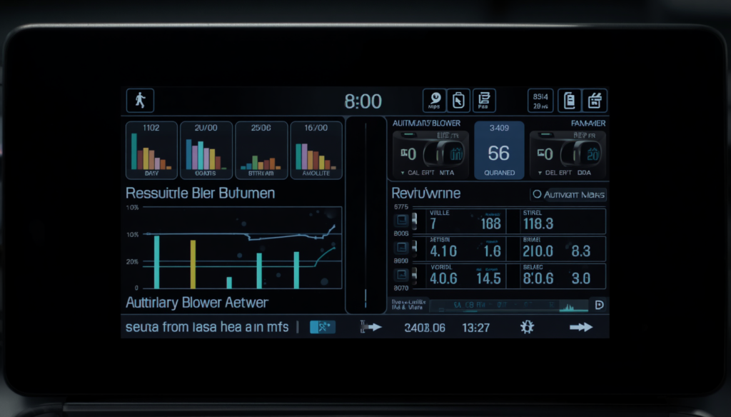
To overcome this bottleneck and make sure manoeuvres are fully Operational Efficiency Driven, modern ships have automated auxiliary blowers and sophisticated variable geometry turbochargers that can sustain high air pressures even at low speeds. All these systems are integrated so that the engine is supplied with a balanced and immediate supply of compressed air during rapid load changes, avoiding incomplete combustion, fuel savings and the lack of substantial black smoke emissions during manoeuvres in port.
Automated Auxiliary Blower Integration
The addition of high power electric auxiliary blowers to the main engine inlet manifold ensures that low speed ship operations are entirely “Operational Efficiency Driven” when handling complex harbour docking manoeuvres. If engine speeds decline and the energy of exhaust gases is insufficient to drive the primary turbocharger, pressure sensors automatically engage these secondary electric fans to provide stable scavenging air pressures. This active air support protects the engine from air hunger to allow complete burning of fuel, providing the captain with fast throttle response and preventing any heavy soot emissions in sensitive coastal port locations.
Variable Geometry Turbocharging Fluid Dynamics
Modern merchant ships can use innovative variable geometry turbochargers (VGT) to fine-tune their intake air systems and maintain outstanding Operational Efficiency Driven throughout all engine speeds. These modern systems employ a set of movable aerodynamic vanes within the turbine housing that automatically modify their angles to regulate the speed of the entering exhaust gases. At low engine speeds the vanes constrict to accelerate weak exhaust flows directly to the turbine blades, immediately accelerating the compressor and maintaining peak efficiency without wasting energy through traditional wastegate valves.
Two-Stage Turbocharging and High-Pressure Intercooling
To push the power limitations of modern environmentally friendly ship engines, multi-stage forced induction networks are needed so that long-distance maritime missions can stay strongly “Operational Efficiency Driven” under tight environmental restrictions. Two-stage turbocharging has air passing between low-pressure and high-pressure compressor wheels in sequence, elevating intake air pressures to a level far higher than single-stage systems can. However , compressing air raises the temperature of the air greatly .
This reduces the density of the air and increases the thermal stress on the engine cylinders . To overcome this physics bottleneck and to maintain the whole system “Operational Efficiency Driven” high capacity water cooled intercoolers are installed between the compression stages to reduce air temperatures. The air volume is reduced and the oxygen density rises by the cooling . Now the high pressure compressor stage can force a dense charge into the cylinders . This maximises engine power production and keeps fuel consumption extremely low .
Sequential and Series Compressor Staging
Series designs of high efficiency turbochargers can support an aggressively “Operational Efficiency Driven” engine cycle for modern cargo ships, enabling operation in difficult deep sea conditions. The initial compressor stage pulls in unprocessed ambient air, applying moderate pressure to it before funnelling the hot air directly into a second, high-pressure compressor stage that amplifies the air density. This two step compression chain reaches pressure ratios that single stage systems can not attain. This allows smaller engines to provide tremendous horsepower outputs while utilising substantially less physical space in the hull.
Intercooler Thermal Loops and Air Density
The entire internal combustion process stays very much “Operational Efficiency Driven” via changing climates by passing highly compressed intake air through huge capacity marine intercoolers. When compressed to high pressures the temperature of air rises sharply and naturally this reduces the total oxygen density and increases thermal stress on key engine valves. This hot air is then passed through a network of copper-nickel tubes cooled by fresh seawater, which decreases the temperature of the air and therefore greatly increases its density, guaranteeing a large, clean charge enters the combustion chamber to maximise efficiency.
The Pulse versus Constant-Pressure Dilemma
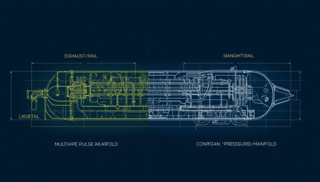
Naval engineers need to be judicious in their routing of exhaust gases into charging systems to ensure a ship’s unique operating profile is “Operational Efficiency Driven” across its multi-decade operational life. Pulse turbocharging systems use individual, small exhaust pipes to direct the high-energy pressure waves from each cylinder straight onto the turbine wheel, making the rotor spin practically quickly for great transient responsiveness.
Constant-pressure turbocharging, on the other hand, collects the exhaust from all cylinders into one huge common manifold, smoothing down the gas flow to a steady, continuous flow that maximises turbine aerodynamic efficiency for long, steady trips. By selecting the most appropriate approach for exhaust routing, customised for the typical route profile of a ship, the whole propulsion plant can run in a very “Operational Efficiency Driven” way, balancing fast throttle response with maximum long range fuel savings.
Pulse Systems for Rapid Transient Flexibility
Specialised pulse turbocharging designs allow ships that often change speeds to retain a highly “Operational Efficiency Driven” engine cycle during frequent manoeuvring. This design employs thin spaced apart exhaust pipes to isolate the high energy pressure waves generated by individual cylinder firings and to direct these focused pulses to the turbine blades. The gas waves hit suddenly, almost at once spooling up the turbine shaft, giving rapid air reaction and good fuel combustion for short-sea vessels like ferries and tugboats that often change speed.
Constant-Pressure Manifolds for Long-Range Steaming
For large deep-sea tankers and cargo vessels, the installation of a wide common-rail constant-pressure exhaust manifold guarantees that extended transoceanic voyages remain incredibly “Operational Efficiency Driven” throughout weeks of steady sailing. In this system the exhaust from all cylinders is discharged into one huge steel receiver tank. The various pressure pulses are averaged out into a constant uniform stream of gas. This constant flow allows the turbine to run at its absolute max aerodynamic efficiency, generating considerable, compounding fuel savings that assist shipping companies manage their long-range operational budgets.
Modern Hybrid Systems and Electrical Assist Technology
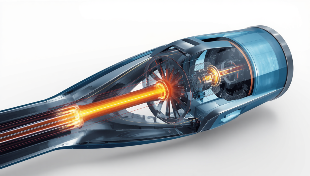
The future of sustainable international marine logistics is a marriage of classic mechanical forced induction and cutting-edge electrical engineering, guaranteeing that modern merchant fleets remain fiercely “Operational Efficiency Driven” in a world of tighter global emission limitations. Today’s hybrid turbochargers use a high-speed electric motor-generator mounted on the common shaft that connects the turbine and compressor wheels.
When the main engine is at full throttle and too much exhaust energy is produced, the system changes into generator mode, harnessing that additional rotational force to supply clean electricity directly into the ship’s main power grid. But in slow-speed port operations, the system functions like an electric motor, rotating the compressor rotor up to maximum air pressure immediately without waiting for exhaust gases to build up. This superior electrical integration means the entire propulsion loop is highly “Operational Efficiency Driven” reducing fuel consumption and lowering emissions in all operating circumstances.
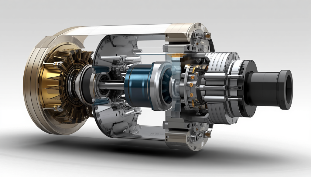
Integrated Motor-Generator Rotor Shafts
Unique “Operational Efficiency Driven” engine configuration at all power levels is made possible for modern commerce ships by the direct mounting of high-speed electric motor-generators on the primary turbocharger shaft. This small electrical link is bidirectional, switching instantaneously between using power to assist the engine and producing clean energy for the ship’s electrical grid depending on real-time throttle needs. The intelligent integration minimises total fuel usage and minimises onboard maintenance protocols by eliminating the mechanical requirement for separate diesel generators when cruising.
Exhaust Energy Recovery Grids
High efficiency hybrid charging systems combined with innovative onboard energy storage networks ensure current vessel activities are aggressively “Operational Efficiency Driven” over long distance transoceanic transits. These hybrid thermal configurations operate in perfect harmony with the data infrastructure outlined in Maritime Digitalization Pathways: Intelligently Automating Large Engines, where real-time power distribution is handled by automated ship-to-shore control loops.
The excess exhaust heat energy of the ship is transformed into electrical power and directly supplied to the main switchboard for the crew’s quarters, reefers and navigation on steady steaming in open waters. The smart heat recovery loop drastically reduces the carbon footprint of a vessel, indicating that recapturing spent exhaust energy is a powerful approach to maximise profitability and meet the stringent modern international environmental regulations.
Conclusion
The historical shift from natural aspiration to advanced exhaust gas turbocharging, underscores the fact that the ocean transport sector has remained firmly “Operational Efficiency Driven” in constructing the infrastructure of modern international trade. Forced induction internal combustion engines could use the waste heat of the exhaust to create huge air compression, giving them a thermal efficiency and power density advantage that the steam propulsion systems of the day could not match.
The shipping industry is under tremendous pressure to convert to alternate, zero-emission fuels, but the mechanical need to maximise air-charging loops remains vitally critical to make logistical networks economical. Advanced, multi-stage turbocharging technology will remain a cornerstone of future alternative energy systems, delivering maximum performance from each unit of fuel. Ultimately, the development and implementation of these high-efficiency air management systems enable the world’s merchant fleet to achieve ambitious decarbonisation targets, while preserving the dependable, low-cost transport infrastructure that underpins global trade.
People Also Ask
Why do marine diesel engines require turbochargers?
Forced induction packs dense oxygen into cylinders, enabling a “Operational Efficiency Driven” cycle that obtains the greatest propulsion power from low-cost residual oil fractions.
How does a hybrid marine turbocharger generate electricity?
When sailing, the surplus exhaust velocity turns a shaft-mounted generator, thus generating an Operational Efficiency Driven power loop that feeds clean electricity back to the vessel.
What is the main difference between axial and radial turbines?
Axial wheels manage large gas volumes for two stroke steaming, while radial units give a ‘Operational Efficiency Driven’ reaction for quick auxiliary generating engines.
How does two-stage turbocharging reduce ship emissions?
The series compression with intercooling produces a “Operational Efficiency Driven” combustion process that maximises the completeness of the fuel burn and thereby reduces soot emission at sea.