Introduction
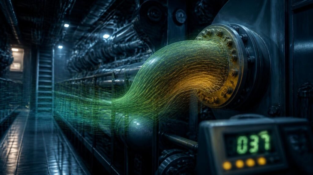
Almost every article on ammonia as a marine fuel ends up at the flammability paragraph. It points out that ammonia burns gradually, the lower explosive limit being about fifteen per cent by volume, and that it is safer than methane. All true, but beside the point. The real figures that govern an ammonia engine room are three orders of magnitude smaller and these are the “ammonia toxicity exposure limits”: 25 ppm, 35 ppm, 300 ppm and the thousands where the argument ends.
Compute it. The lower explosive limit is about 150,000 ppm. 300. A watchkeeper is in urgent danger. That is incapacitation at one five-hundredth of the concentration at which the fuel becomes a fire hazard. The lesser number dictates every bulkhead, every fan, every sensor, every escape path. You design a ship that complies with the flammability case . Then you poison people .
That’s why ammonia toxicity exposure limits warrant their own essay. They are not health-and-safety boilerplate tacked on to a finished design. They are the input that governs. Keep that in mind and the layout questions will answer themselves in a sequence unlike anything studied on LNG.
Here is the walk through the four governing values, the odour threshold trap that sounds like a control and isn’t, the dispersion modelling behind your deck footprint, the alarm cascade that turns concentration into machinery, and the toxic space rules that rewrite how anyone enters the compartment.
Table of Contents
Why parts per million govern and the explosive limit does not

Marine engineering has a century of custom directed at ignition. Hot surfaces, flashpoint, zone classification, spark-free instruments. Ammonia does burn but it burns grudgingly and it’s really cheap to close that argument. The ‘ammonia toxicity exposure limits’ open a second and far more demanding can, because they kick in at quantities unseen to any flammability sensor. A design optimised for explosive limits gets its own review and nevertheless puts watchkeepers in a space where a small leak is disabling in a few of breaths.
Ammonia toxicity exposure limits sit three orders below the fire case
Put the numbers next to one another and the design rationale is apparent. The lower explosive limit is about fifteen percent by volume. That’s about 150,000 parts per million. The occupational standard is 25 ppm. The immediate danger level is 300 ppm, a figure the Ammonia as a Marine Fuel Safety Handbook ties to dangerous consequences on exposure. The ratio of fire number to hurt number is approximately five hundred to one. No other marine fuel has such a gap. The flammability case is conservative enough to safeguard persons inadvertently on diesel or methane, so designers never had to consciously separate the two concerns.
Why ammonia toxicity exposure limits become the governing design input
The input governing is the parameter that moves anything downstream when it’s altered. In an ammonia machinery space that parameter is concentration. The ventilation rate is sized to maintain the concentration below a threshold. The sensor placement is chosen to sense an increase toward a threshold. A human can only stay in a rising cloud for a limited time, which determines the bulkhead position, airlock location and length of escape route. Change your accepted threshold by fifty parts per million and the fan sizing, the duct routing and the alarm philosophy all change with it.
The four numbers that define your design envelope
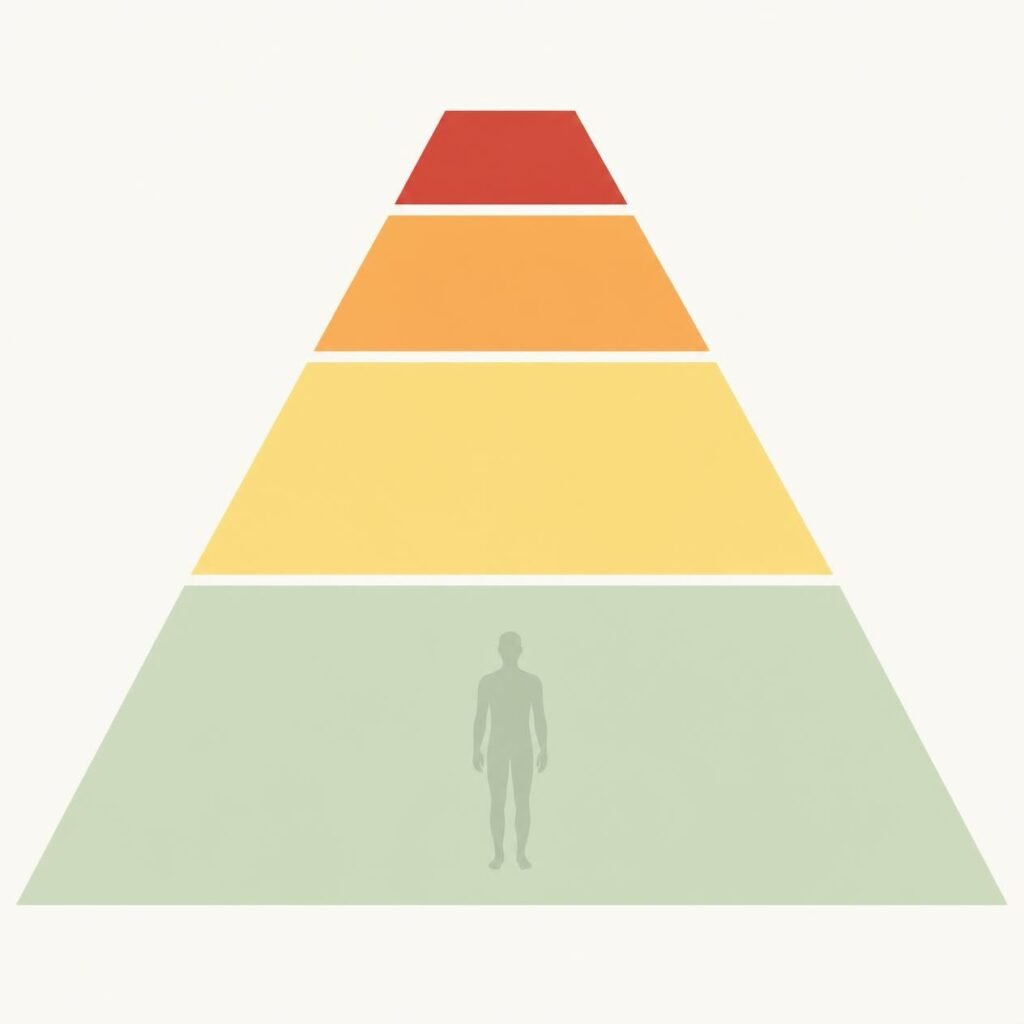
Four values do practically all the work. The eight-hour time-weighted average of 25 ppm, the short-term exposure limit of 35 ppm, the immediately harmful to life and health value of 300 ppm, and the acutely deadly band starting in the low thousands. These “ammonia toxicity exposure limits” delineate a design envelope: the levels to which one can be subjected continuously, for a short while, with breathing apparatus, or to kill before anyone can reach a door. Everything else is measured against those four values.
TWA and STEL, the chronic ammonia toxicity exposure limits
The 25 ppm time-weighted average is the concentration to which a person can be exposed during an entire working shift without foreseeable significant injury, and the 35 ppm short-term exposure limit covers momentary excursions above that. American occupational regulation has an allowed exposure limit of 50 ppm over eight hours . This is why published values vary from source to source . The “ammonia toxicity exposure limits” are chronic-exposure figures for routine operation, not emergency. They are the values a surveyor will verify initially and they determine your continuous ventilation obligation and lowest alarm threshold.
IDLH and lethality, the acute ammonia toxicity exposure limits
At levels above 300 ppm the paradigm shifts from exposure control to escape and rescue. That value is the maximum above which it is impossible for an individual to self-evacuate with certainty without respiratory protection and at which positive-pressure breathing apparatus is necessary for admission. Published marine research indicate that about 1,600 ppm over a period of about thirty minutes creates life threatening effects. 5,000 ppm and above risks respiratory arrest regardless of the time involved. Skin burns develop upon contact above 10,000 ppm. These upper ammonia toxicity exposure limits size your escape time greater than your fan capacity.
The odour threshold trap

Ammonia is recognised by its strong odour, which can be detected at about two to five parts per million. That is substantially below all of the “ammonia toxicity exposure limits”. That sounds reassuring and is sometimes misunderstood as a built-in warning mechanism. The consoling conclusion is that a crew will smell a leak and go away. The comfort is misguided, but not for the reasons most people think. Detection isn’t the weak link. Physiology of the nose, duration of exposure and interpretation is.
The odour threshold and what it tells you about ammonia toxicity exposure limits
Ammonia advertises its presence at two to five parts per million long before it may hurt anyone. This is a helpful characteristic, and accounts for ammonia’s better incidence record than odourless dangerous gases at same concentrations. But a warning property is not a control measure. It is a physiological response with no calibration, no logging, no alarm contact and no ability to cause a shutdown. Nothing about a human nose can be tested, recorded or proved to a surveyor, hence it cannot be used in a safety case as an instrument.
Why smell fails where instrumented ammonia toxicity exposure limits succeed
There are three things that break the scent argument in practice. Olfactory fatigue reduces the response on prolonged exposure, so the person with the greatest exposure is the least able to judge. A leak under pressure in a restricted equipment space might go from noticeable to harmful faster than a person can cross the gap. And smell gives no number . So a crew member can’t tell the difference between a nuisance seep and a developing emergency . Instrumentation translates a sensation into a value that can be compared to “ammonia toxicity exposure limits”. Only a value can be acted upon consistently.
Dispersion modelling and the toxic cloud on deck
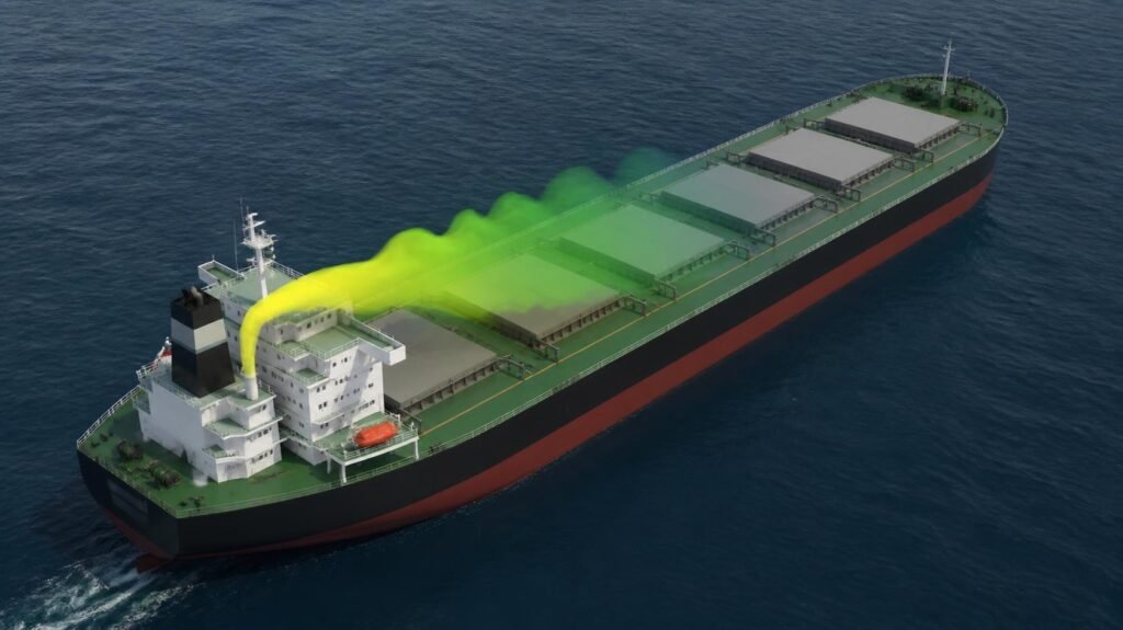
Concentration in a space is only half the challenge. All that comes out has to go somewhere, and whether it is the bridge, the accommodation intakes or the lifeboat stations, it has to be a place where it becomes uninhabitable. Dispersion modelling uses the release rate, the ventilation flow, the discharge geometry and the wind, and generates a forecasted footprint against the “ammonia toxicity exposure limits”. It is that footprint, not any of the regulation wording, that determines where you can safely locate a muster point, an air intake or an escape door.
Source term and release rate against ammonia toxicity exposure limits
The source phrase is where modelling lives or dies. A vapour leak from a low pressure line is considerably different from a flashing liquid leakage out of a chilled system at minus thirty three degrees. Ammonia vapour is lighter than air, and this encourages designers to think that it would rise and disperse harmlessly. A flashing liquid discharge does not do this as the mixture of aerosol and cold vapour first behaves like a thick gas and hugs the deck. Pick the wrong source phrase, and every downstream comparison to “ammonia toxicity exposure limits” will be wrong.
Wind, footprint and re-entrainment under ammonia toxicity exposure limits
Once the cloud leaves the vent mast, the variables are environmental. Concentration areas are influenced by wind speed and direction, the relative wind from the vessel’s own movement, superstructure turbulence and the pressure field around the accommodation. One specific failure mode to look for is re-entrainment where the intake of air draws the discharged vapour straight back in. The modelling has to capture the worst cases, not the average day. The unfavourable case is the one that sends concentrations above the “ammonia toxicity exposure limits” across an escape route or a muster station.
Alarm setpoints turn limits into machinery
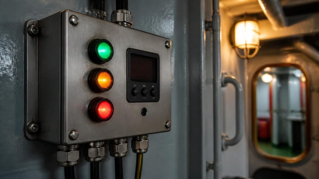
Exposure numbers are only engineering when wired to anything. The IMO interim guidelines describe a progressive alarm method, local alarms at ca. 25 ppm, wider vessel alarms at ca. 110 ppm and system shutdown at ca. 220 ppm. That cascade is where “ammonia toxicity exposure limits” stop being health data and become control logic, dictating detector placement, voting schemes, ventilation boost, and the point at which the fuel system separates itself autonomously. Each threshold requires justification, not inheritance.
The graduated alarm cascade built on ammonia toxicity exposure limits
A single alert point would be meaningless, because the response to a seep is quite different to the response to a rupture. A graduated cascade assigns increasing actions to concentration bands: investigate, muster and ventilate, isolate and evacuate. Each step has to be justifiable in terms of the underlying values, i.e., the designer has to explain why a specific setpoint was selected and which response time this assumes. One common review finding class is setpoints borrowed from a sibling project without justification against the “ammonia toxicity exposure limits”.
Vent mast discharge and the ammonia toxicity exposure limits at the outlet
Published marine dispersion work recommends treating or capturing released ammonia so the concentration at the vent mast discharge remains low, with figures of around thirty parts per million proposed as a working figure, and notes that the IGF Code does not yet specify an acceptable release concentration. So the class societies have chosen slightly different cut-offs. That discrepancy is commercially significant, because a design acceptable to one civilisation may need modification for another, and the difference often manifests as additional treatment equipment, sized against whatever “ammonia toxicity exposure limits” the society imposes.
Toxic space and how it rewrites access control
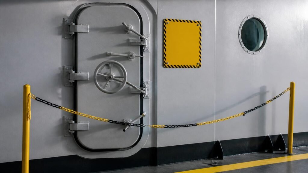
In addition to the usual hazardous-area approach, the interim rules introduce the classification of toxic regions and dedicated sections on prevention of exposure to toxicity and on personal protection. A toxic area is one where “ammonia toxicity exposure limits” may be exceeded, and the designation entails implications. Entry becomes a regulated procedure instead of a walk. The line between a poisonous space and a safe space becomes no longer a line on a design but a physical engineering feature.
Defining a toxic space around ammonia toxicity exposure limits
Classification is not ornamentation. Once a room is declared to be toxic, the entire manner in which humans interact with that space changes. Ventilation must be independent, doors may not open directly into safe regions without an intermediate barrier, and entry requires monitoring and breathing gear adequate to the anticipated concentration. The definition is ultimately based on concentration, therefore the boundary for the categorisation is drawn where the ‘ammonia toxicity exposure limits’ suggest it should be, not where the arrangement drawing finds it handy. This turns classification into a real design decision, not just an exercise in labelling.
Airlocks, entry discipline and ammonia toxicity exposure limits in practice
Airlocks are the physical embodiment of the classification. The airlock is designed such that the pressure differential is maintained and not both doors can be open at the same time. A location for a person putting on protective gear to stand is also defined. The procedural part is the entry discipline. Pre-entry gas measurement, a standby person outside, a communication technique that truly works with a mask on, a recorded permit. Operators from a typical tonnage background routinely underestimate the impact on routine maintenance of working inside the “ammonia toxicity exposure limits” and both the schedule and personnel impact should be considered early.
Translating concentration into a machinery space layout
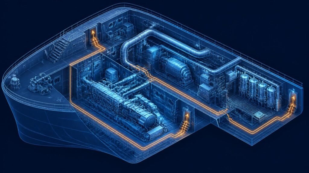
This whole lot of analysis is paid off by a layout that can be defended line by line, which is precisely what Ammonia fuel safety case, Why an ammonia engine room needs a safety case, not a checklist sets out to build. In an ammonia engine room every significant arrangement decision boils down to a concentration value and a time. How long is the furthest distance to a safe place on foot. How long is that in PPE? What concentration will be on that route at that time. “Ammonia toxicity exposure limits.” That turns each of those enquiries into figures a designer can engineer to.
From ammonia toxicity exposure limits to bulkhead and equipment positions
Start with the individual. Fix the maximum tolerable exposure in the escape, then the time available, then the distance that time permits in breathing apparatus, then the bulkhead and door positions follow. The same reasoning sizes ventilation as the fan needs to keep concentration under the threshold at the modelled release rate. Wherever possible, equipment that requires frequent attendance should be located outside the poisonous boundary. This is because each routine activity conducted within the “ammonia toxicity exposure limits” boundary becomes a permission, a gas test, a standby man and a delay that multiplies over a docking.
Escape routes, muster points and ammonia toxicity exposure limits on deck
This is where the internal and exterior analysis meets in escape planning. A route that pulls a crew person out of a machinery room and straight into the modelled deck footprint has solved nothing. Muster sites, lifeboat stations and the accommodation air intakes all need to be checked against the projected cloud under unfavourable wind. Providing safe refuge is also important, because in some release situations a shelter behind a gas-tight border with an independent air supply maintains a crew below the “ammonia toxicity exposure limits” far more reliably than sending them across an open deck.
Conclusion
The industry continues to quote flammability figures because they are known and comforting. And are of almost no consequence to the actual lay-out of an ammonia engine room too. The real design drivers are “Ammonia toxicity exposure limits” which are around 3 orders of magnitude lower than the fire example. Get the numbers right on the concentration and the layout comes naturally from this. Get them wrong and no amount of flammability compliance will save the individuals who have to stand a watch in that space.
People Also Ask
What are the key ammonia toxicity exposure limits a designer must work to?
25 parts per million as an 8-hour average 35 parts per million as a short-term limit 300 parts per million as instantly harmful to life and health. The low thousands begin to have lethal effects, with respiratory arrest being a possibility at around five thousand and above.
Why do published ammonia toxicity exposure limits differ between sources?
Various bodies have distinct goals for setting values. Different averaging times and safety margins are used by occupational hygiene organisations and national regulators hence eight hour numbers of twenty five and fifty parts per million exist both legitimately in the literature depending on the jurisdiction.
Can smell be relied on instead of detectors given ammonia toxicity exposure
” No. Ammonia can be detected from around two parts per million, far below the danger limits, however olfactory fatigue, quick rise of concentration and no measurable value make smell worthless as an engineering and auditable control measure aboard any ship.
How do ammonia toxicity exposure limits affect escape route design?
They decided the time budget. The maximum tolerated exposure defines the survivable duration. Duration determines the feasible distance in breathing apparatus and that distance determines the bulkhead positions, the door locations and how far any muster point may realistically be from the space.