Introduction
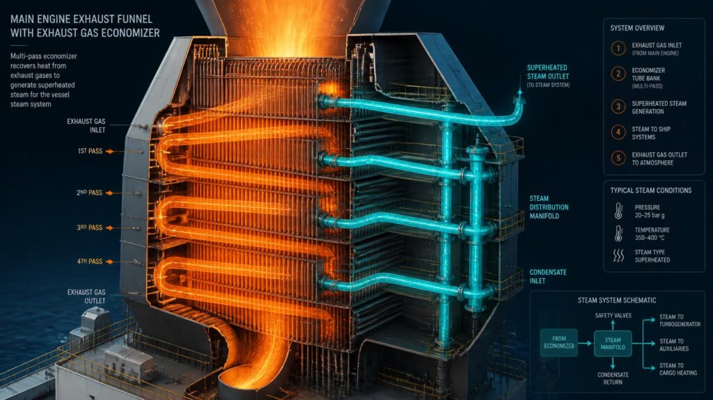
With worldwide decarbonisation standards rising relentlessly, engine room thermal management has become a key driver for commercial vessel compliance. Modern crosshead two-stroke engines expel large quantities of thermal energy via their exhaust streams that would normally be lost to the atmosphere if not captured. At the heart of this technical change are “Waste Heat Recovery Systems”: Capturing Thermal Exhaust Loss to Unburden Auxiliary Boiler Fuel Burn.
As analyzed in Waste heat recovery from marine engines and their limiting factors: Bibliometric analysis and further systematic review, technical operators can capture this stranded thermal energy by adding more exhaust gas ducting, adding improved exhaust gas economiser matrixes, and adding automated steam management valves. The incorporation of modern “Waste Heat Recovery Systems” can ensure vessels meet all hotel and fuel oil heating loads while underway, thereby eliminating all auxiliary boiler fuel burn and directly impacting the numerator of the Carbon Intensity Indicator (CII) equation.
The Thermodynamic Imperative of Exhaust Thermal Harvesting
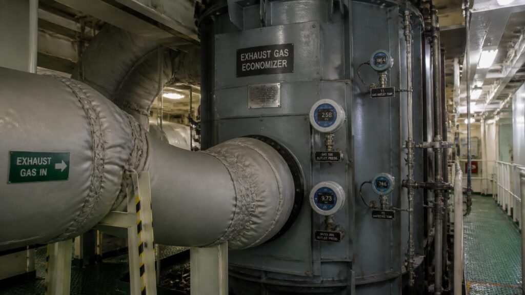
In two-stroke engines only a small part of the chemistry released during the burning of the fuel is used as effective power of the propeller shaft, a considerable share of the energy being wasted in the form of high-temperature exhaust gases. Auxiliary oil-fired boilers have to run continually to supply steam for heavy fuel oil heating, cargo temperature maintenance and domestic accommodation loads if there is no thermal reclamation. High-efficiency “Waste Heat Recovery Systems” upgrade vessel infrastructure by capturing this fleeing energy stream directly within the exhaust trunking. By reclaiming thermal energy, it decreases the consumption of secondary fuels, transforming wasted exhaust heat into an active defence against carbon rating degradation during operation.
Reclaiming Stranded Energy to Lower the CII Numerator
The Carbon Intensity Indicator computation is directly related to the total mass of carbon dioxide emitted per nautical mile sailed. Every litre of fuel oil that auxiliary boilers burn for thermal energy either in port or at sea is added directly to the overall carbon output, and not one single knot of vessel distance contributes to the total. Introduction of dedicated “Waste Heat Recovery Systems” that use waste thermal energy to produce process steam allowing operators to shut down auxiliary burners during sea transits. The use of “Waste Heat Recovery Systems” to harness this energy reduces overall daily emissions and protects the vessel’s annual rating.
Counteracting Low Exhaust Gas Temperatures from Slow Steaming
Operating the vessels at slow speeds reduces the power output of the main engine, which reduces the temperature of the exhaust gases below the limits for the classic design of the economiser. Under these low load conditions conventional heat exchangers cannot generate sufficient steam pressure and auxiliary boilers are ignited to compensate the steam shortage. Upgrading to modern “Waste Heat Recovery Systems”: with additional heat transfer surface areas to compensate for lower exhaust temperatures. Use of “Waste Heat Recovery Systems” Enables continuous steam generation in slow steaming transits, avoiding fuel burn spikes.
Modifying Exhaust Ducting and Economizer Matrix Layouts
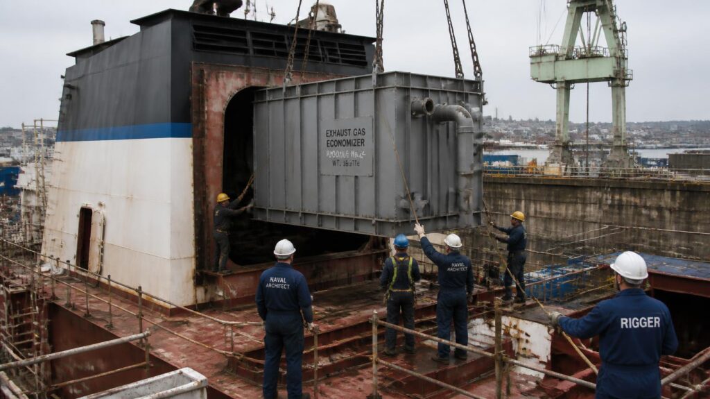
Retrofitting of an over-sized or additional exhaust gas economiser will necessitate modifications to the structural casing of the ship and the main engine ducting arrangements. Technical management teams need to consider exhaust gas velocity, backpressure restrictions and space constraints to prevent excessive flow resistance that could impair engine turbocharger efficiency. Maximum thermal transfer efficiency can be achieved with sophisticated composite tube bundles or small extended-surface heat exchangers in limited engine room footprints. Retrofit structural casing components to fit “Waste Heat Recovery Systems”: offers a long-term mechanical solution for thermal energy capture.
Managing Exhaust Gas Backpressure and Scavenge Air Balance
Increasing the surface area of heat exchanger tube banks inside the exhaust trunking will inevitably introduce fluid friction, which increases overall engine backpressure. Excess backpressure hinders scavenging air passage thru the cylinder exhaust valves, causing an increase in thermal stress on the piston crowns and a decrease in the effectiveness of the turbocharger. Engineering modern Waste Heat Recovery Systems involves accurate hydrodynamic modelling to guarantee that pressure reductions in the gas are well within manufacturer tolerances. Adding aerodynamic ducting profiles to “Waste Heat Recovery Systems”: maintains main engine scavenging efficiency, so thermal harvesting does not come at the expense of main engine health.
Advanced Extended-Surface Tube Geometry and Compact Footprints
Replacing smooth-bore steel tubes with gilled, finned, or spiral tube geometries dramatically enhances the effective heat transfer surface area without increasing the exterior shell dimensions of the economiser. This compact design innovation permits big capacity heat exchangers to be fitted into the constrained funnel casings of current fleet assets. Modern “Waste Heat Recovery Systems”: features these sophisticated tube profiles for optimising the absorption rates of thermal energy from low temperature gas flows. Utilising tiny “Waste Heat Recovery Systems”: allows vessels, even with limited space, to utilise the thermal kilowatt production from their exhaust stream to the most extent.
Automated Steam Management and Dump Valve Integration
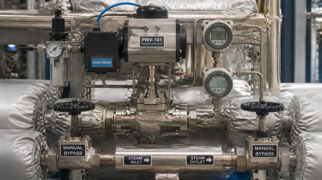
Intelligent steam distribution architecture, able to balance variable onboard heat demand against varying thermal supply is necessary for efficient thermal reclamation. High loads on the primary propulsion engine can produce exhaust heat greater than the immediate steam demand of the vessel, which could result in hazardous over-pressurization of the economiser. Automated steam management valves and dump condensers can be installed to transfer excess steam to specialised dump coolers or central feedwater tanks. Modernised control of “Waste Heat Recovery Systems”: Ensures stable functioning over the whole engine load range.
Dynamic Pressure Regulation and Excess Steam Dumping
Automated steam management systems constantly monitor the steam drum pressure and actuate proportional control valves to ensure stable operating pressures in the face of varying main engine loads. When the main engine production increases, excess steam is routed thru automatic dump valves to an air-cooled or seawater-cooled dumping condenser. “Waste Heat Recovery Systems”: Embedded dynamic control loops and avoiding safety valve lifts and ensuring accurate regulation of steam pressure for fuel oil heating. By clever “Waste Heat Recovery Systems” – ensures flawless steam supply regulation without the need for manual intervention by engine room watchkeepers.
Protecting Feedwater Circuits and Condensate Quality
Condensate returned from heavy fuel oil heating coils and household calorifiers must be continually checked for oil contamination or chemical impurities before to entering the economiser feedwater circuit. The high temperature economiser tubes are susceptible to rapid scaling and localised overheating failures caused by thermal stress or oil contamination. The polluted condensate is automatically diverted away from the steam drum by integrating oil-in-water detection sensors with “Waste Heat Recovery Systems”. The “Waste Heat Recovery Systems” maintain feedwater integrity, extending economiser tube service life and avoiding expensive boiler retubing overhauls.
Dual-Pressure and Organic Rankine Cycle Integration
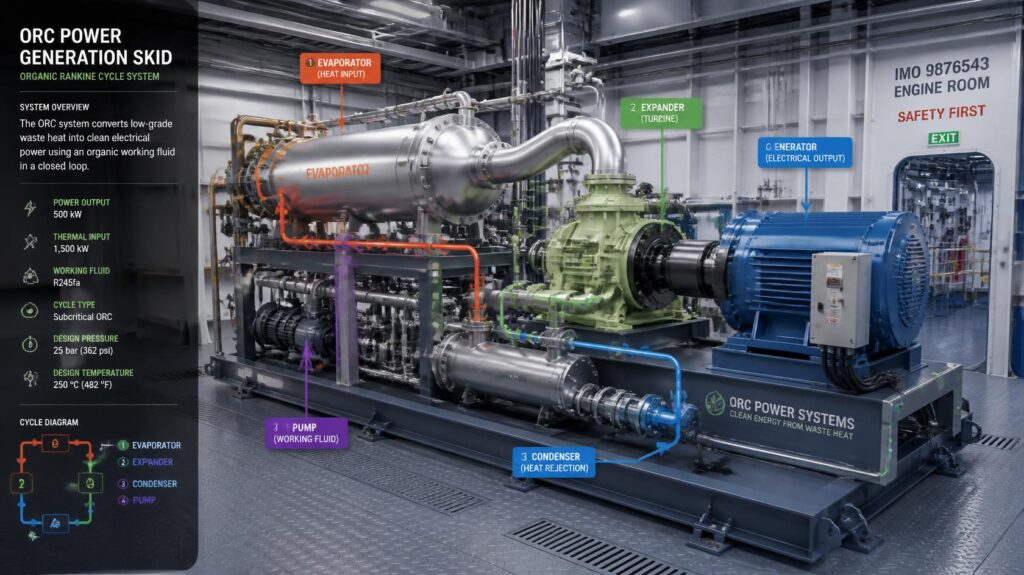
Advanced multi-stage thermal harvesting architectures can be used to upgrade standard single pressure steam economisers for high powered vessels requiring optimal thermodynamic efficiency. Dual-pressure steam systems can provide high-pressure steam for heavy heating activities and low-pressure steam for auxiliary machinery or turbo-generator electrical power generation. Alternatively, Organic Rankine Cycle (ORC) machines use organic working fluids with low boiling points to produce clean power from low-temperature exhaust and jacket cooling water. The use of these complex thermodynamic cycles into the current “Waste Heat Recovery Systems” unleashes unparalleled levels of fuel efficiency.
Electricity Generation via Steam Turbo-Generators
High-pressure steam taken from an extended economiser matrix is used by technical staff to drive an onboard steam turbo-generator that provides a large part of the ship’s electrical hotel load. This configuration reduces electrical load on auxiliary diesel generators for a compounded reduction in total daily fuel mass use. Combined-cycle “Waste Heat Recovery Systems” propulsion plant upgrades: converts waste heat directly into useable kilowatt hours of electrical power. Introduction of turbo-generator integrated “Waste Heat Recovery Systems”: Provides a feasible technique to reduce the total fuel oil consumption under way.
Harnessing Low-Grade Jacket Water Thermal Losses
In addition to exhaust gas, Organic Rankine Cycle systems collect heat from primary engine jacket cooling water and charge air coolers. The organic fluid is sent thru compact heat exchangers to vaporise it at low temperature, which then drives miniature expander turbines. ORC skids as part of complete “Waste Heat Recovery Systems”: recover low-grade thermal losses from across the propulsion plant that were not previously recoverable. Multiple source “Waste Heat Recovery Systems” maximise overall thermal efficiency and convert low temperature waste heat into constant electrical power.
Soot Blowing, Fire Prevention, and Maintenance Integrity
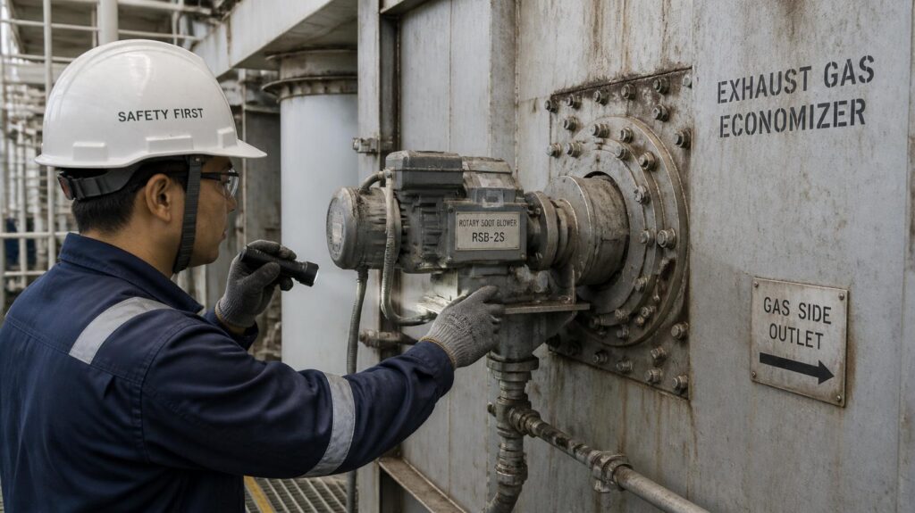
Over extended transits, the accumulation of unburned soot particles on economiser heat transfer surfaces functions as an insulating blanket that drastically degrades thermal absorption efficiency. Also, dried deposits of soot mixed with unburned gasoline or carryover of cylinder lubricant constitute a major fire threat in the exhaust casing if localised temperatures rise. Automated steam soot blowers or ultrasonic horn acoustic cleaners are installed to keep the tube surfaces free of insulating carbon deposits. • Implementation of strict maintenance procedures on “Waste Heat Recovery Systems”: protects heat transfer rates and eliminates the threat of catastrophic soot fires.
Automated Steam Soot Blowing and Soot Fire Mitigation
Automated soot blowing systems fire pulses of high pressure steam across tube banks at pre-set intervals to blow loose carbon deposits off the heating surfaces before they harden. Regular soot removal preserves maximum thermal conductivity, preventing the loss of heat exchanger performance during long maritime transits. As detailed in Cylinder Lubrication Management: Reducing Unburned Hydrocarbon Smoke to Safely Protect Your AER Score, automated soot cleaning prevents accumulation of unburned oil that causes deadly high-temperature soot fires in “Waste Heat Recovery Systems”. Maintaining clean tube bundles safeguards valuable capital equipment and maximises daily steam production
Infrared Fire Detection and High-Pressure Water Washing
Modern economisers have localised infrared fire detection sensors and specific high pressure deluge water spraying nozzles to immediately douse thermal runaways. During planned port calls, technical crews perform routine water washing of the economiser matrix to neutralise corrosive sulphur soot deposits and re-establish clean metal contact. “Waste Heat Recovery Systems”: integration of safety systems and cleaning procedures protects personnel and infrastructure in the engine room. “Waste Heat Recovery Systems” : Prioritising safety measures for reliable operational readiness over strict business timelines.
Economic Payback and Carbon Intensity Compliance
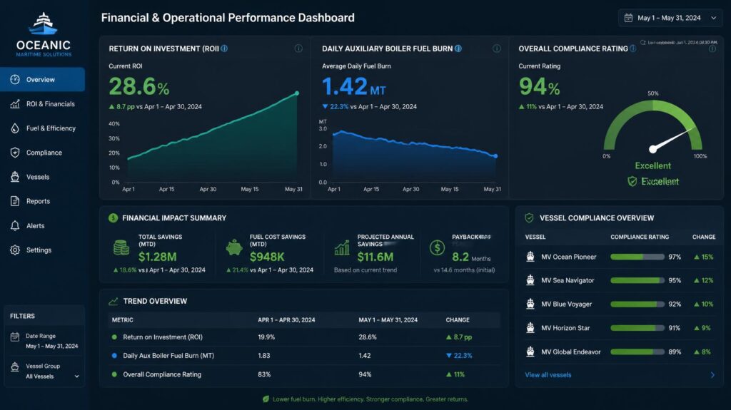
Large capacity exhaust ducting retrofits and automated steam management systems require a clear financial justification based on demonstrable fuel cost savings. During sea transits, the complete unloading of oil powered auxiliary boilers reduces fuel oil consumption by 2 to 6 tonnes a day, depending upon the size of vessel and heat requirement. With the high pricing of the marine fuels, the capital expenditure for the economiser improvements is often recovered within 18 to 36 months of continuous operation. Target-driven deployment of “Waste Heat Recovery Systems”: fast financial payback, permanent securing of compliant CII operating grades.
Offsetting Fuel Expenses and Operational Costs
Vessel managers can achieve immediate reductions in operating expenditure by eliminating the continual burning of expensive Low Sulphur Fuel Oil or Marine Gas Oil in auxiliary boilers. Financial savings from harvesting free exhaust heat directly cover the initial drydocking conversion costs. Investing in modern “Waste Heat Recovery Systems”: Converts unproductive exhaust streams into important drivers of everyday operational profitability. • Long term savings in fuel using “Waste Heat Recovery Systems” reinforce the vessel’s business position in competitive charter markets.
Securing Charter Party Advantages via Verified Efficiency
Corporate Scope 3 emissions targets are driving commercial charterers to seek vessels with demonstrated low carbon intensity profiles. Higher daily charter rates and preferred employment terms are achieved by ‘A’ and ‘B’ rated tonnage with good waste heat recovery. – Installation of Certified “Waste Heat Recovery Systems”: Provides verifiable proof of improved thermal efficiency during charter negotiations. “Waste Heat Recovery Systems” validated, protecting fleet assets from early commercial obsolescence with high asset liquidity and resale value.
Future-Proofing Thermal Management Strategies Beyond 2026
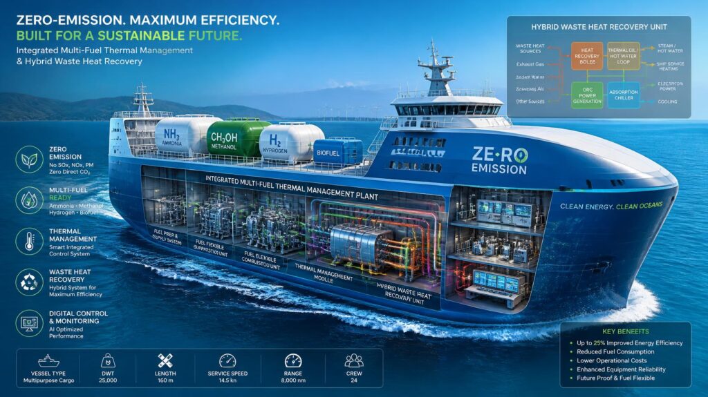
However, as the international emission reduction targets become tighter and tighter toward 2030 and beyond, the commercial viability of using supplementary fossil fuel burning would go down. Shipowners need to build thermal energy management architectures that can be smoothly integrated with future low and zero carbon propulsion fuels. Dual fuel engines running on methanol, ammonia or LNG have variable exhaust gas thermal profiles requiring adaptable heat recovery designs. Fleet asset upgrades with adaptive “Waste Heat Recovery Systems”: builds a flexible base for future green fuels, assuring continued operational compliance beyond the fleet lifetime.
Adapting to Alternative Fuel Exhaust Thermal Profiles
Alternative fuels in the marine sector have various combustion properties, e.g., methanol and ammonia produce different emissions of exhaust gas and moisture content than heavy fuel oil. The design of modern heat exchangers for alternative combustion products needs corrosion-resistant alloys and variable-geometry dampers for safe operation. The modern design of “Waste Heat Recovery Systems” with the option to use different fuels offers long-term operational flexibility. Implementation of multi-fuel compatible “Waste Heat Recovery Systems”: Protects existing capital expenditures against future regulatory and technological changes.
Establishing Integrated Energy Management Infrastructures
The future ship will have centralised energy management software that dynamically allocates captured thermal energy to electricity generation, cabin HVAC, and fuel preparation systems. The waste heat recovery system real-time telemetry and control allows the operator to allocate energy in respect to the real-time sea state and power requirements. Digital Analytics Embedded in “Waste Heat Recovery Systems” Maximise Total Plant Efficiency Without Increase in Crew Workload. Adopting modern “Waste Heat Recovery Systems”: puts ship management firms at the cutting edge of sustainable maritime engineering.
Conclusion
Maximizing thermal efficiency through waste heat reclamation is a crucial technique for modern fleet managers facing tough decarbonization requirements. Uncaptured exhaust loss is a direct cost and environmental consequence, increasing auxiliary boiler fuel use and adversely affecting a vessel’s Carbon Intensity Indicator rating. Retrofitting high capacity economisers, modifying exhaust ducting and incorporating automated steam management valves all convert waste thermal energy into process steam. The investment into “Waste Heat Recovery Systems”: Instant fuel savings, relief for auxiliary boilers and compliant operational ratings for commercial shipping worldwide.
People Also Ask
How do Waste Heat Recovery Systems: lower a vessel's annual CII rating?
“Waste Heat Recovery Systems” application: collects thermal exhaust energy for process steam, no auxiliary boiler fuel consumption in sea transits. This reduces the numerator of the CII calculation, leading to a reduction in overall carbon emissions.
Can Waste Heat Recovery Systems: generate sufficient steam during slow steaming transits?
Yes. Upgrading to modern ‘Waste Heat Recovery Systems’: with extended-surface finned tube geometries increases heat transfer surface area, allowing successful steam generation even from lower-temperature main engine exhaust gas flows.
How do automated steam dump valves protect Waste Heat Recovery Systems: from over-pressurization?
“Waste Heat Recovery Systems” use automated steam dump valves that constantly monitor the pressure of the steam drum and automatically dump surplus steam to a condenser during high main engine load circumstances to maintain stable pressure without the need to lift safety valves.
What is the typical payback period for installing upgraded Waste Heat Recovery Systems: on commercial ships?
Installing contemporary “Waste Heat Recovery Systems”: saves 2 to 6 tonnes of auxiliary boiler fuel per day while at sea, often gives complete financial return in 18 to 36 months.