Introduction
The modernisation of big two stroke marine propulsion systems is mainly concentrated on the deletion of the traditional mechanical camshaft and the implementation of innovative high pressure fluid networks. At the very vanguard of this technological shift is a very specialised, tiny component frame called the Hydraulic Cylinder Unit. To properly bridge the gap between these physical components and digital networks, a complete ME Engine Control System Overview is necessary to understand how the HCU interfaces with the core computer.
This engineering guide will methodically analyse the physical architecture, internal modules and spatial arrangement that characterise this crucial machinery space. By studying these deep details, technical managers will get an “Exclusive InsideLook Guide” on how modern merchant vessels control massive cylinder forces with accurate, software-directed hydraulic block assemblies.
Table of Contents
The Core Architecture of the HCU Block
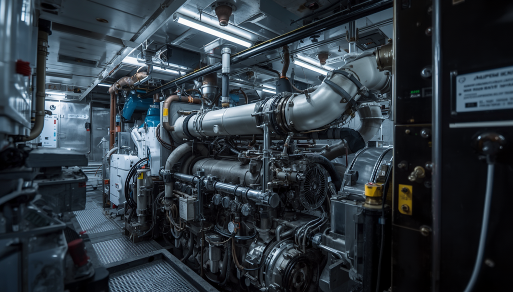
On a modern electronic main engine, each cylinder will have its own totally independent and fully contained Hydraulic Cylinder Unit assembly. This particular cast steel block structure is a central manifold which directs high pressure hydraulic servo oil straight to the various functioning actuators below it. The reviewed design offers a “Exclusive InsideLook Guide” to the essential backbone of today’s camshaftless propulsion systems. The compact manifold arrangement was mounted immediately on top of the engine frame gallery level. This significantly reduced the pipe lengths and improved the efficiency of fluid gearbox.
Structural Manifold Design
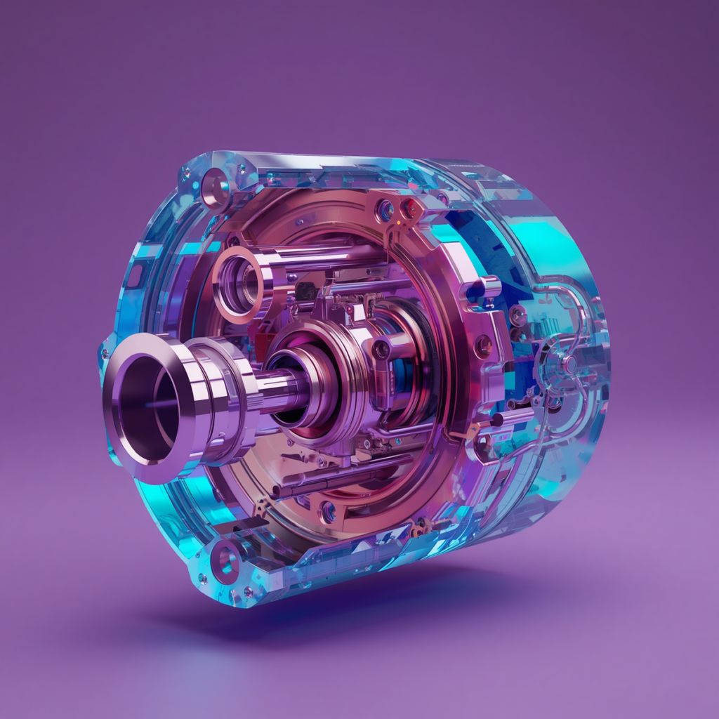
The main physical body of the unit is precision machined from a single block of high tensile cast steel to prevent structural faults under excessive internal pressure changes. This monolithic assembly has a complex network of internal bored channels that completely eliminate the need for standard external high pressure hydraulic piping lines. The “Exclusive InsideLook Guide” opens the eyes of marine superintendents to the extent this clever internal channel design can significantly reduce the risk of high pressure oil spills in the engine room. This heavy duty manifold architecture offers absolute structural stiffness under constant cycle stresses.
Top Gallery Spatial Placement
The unit is securely bolted to the upper structural frame of the engine, so that it sits exactly next to the cylinder cover it controls. This position is advantageous in that the orifices for the high pressure fluid are located near the fuel injectors and the exhaust valve housing. Those technical operators who read this “Exclusive InsideLook Guide” will soon realise how important it is to reduce this physical distance in order to reduce hydraulic lag during high-speed engine operations. This local placement ensures the control signals to be immediate mechanical actions with minimum pressure drop.
Decoupled Modular Integration
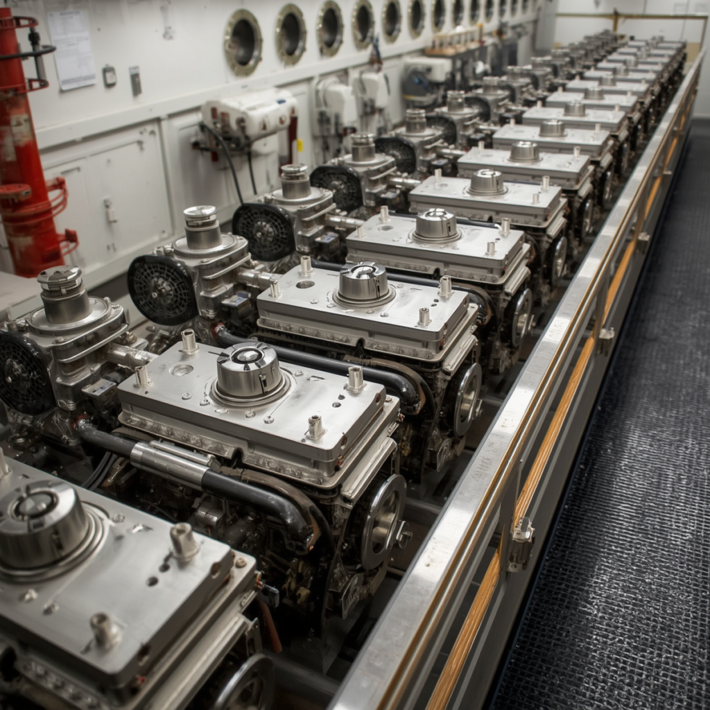
The principle of modern electronic main engines is that each cylinder unit is completely independent of the rest of the propulsion system. When one mechanical part fails locally, the other units can still work regularly to safely propel the vessel to its next location. This modular method provides a “Exclusive InsideLook Guide” to the latest marine safety and redundancy engineering concepts. This separation of the critical operational control blocks allows vessel operators to identify specific cylinder defects without a full propulsion plant outage.
The Per-Cylinder Split Philosophy
In the old days, all the gasoline pumps in a conventional engine were driven by one solid camshaft, so a localised mechanical failure could knock out the whole equipment plant. The electronic layout completely eliminates this single-point vulnerability by having each individual cylinder its own completely independent and dedicated HCU block. Chief engineers who depend on this “Exclusive InsideLook Guide” know that this smart setup offers exceptional operational safety margins for long deep sea journeys. This entire separation means each cylinder can operate with its own timing maps based on the mechanical condition of that cylinder.
Independent Isolation Capabilities
Engine control software enables engineers to securely remove an internal component within an HCU block if a serious leak or electronic malfunction occurs. The other cylinders will then automatically change their fuel delivery schedules to compensate for the loss of power, while yet maintaining structural balance safe. This “Exclusive InsideLook Guide” teaches technical staff how to immediately bypass physical requirements by using software settings on the fly. This outstanding isolation feature allows the vessel to safely reach a port for targeted maintenance.
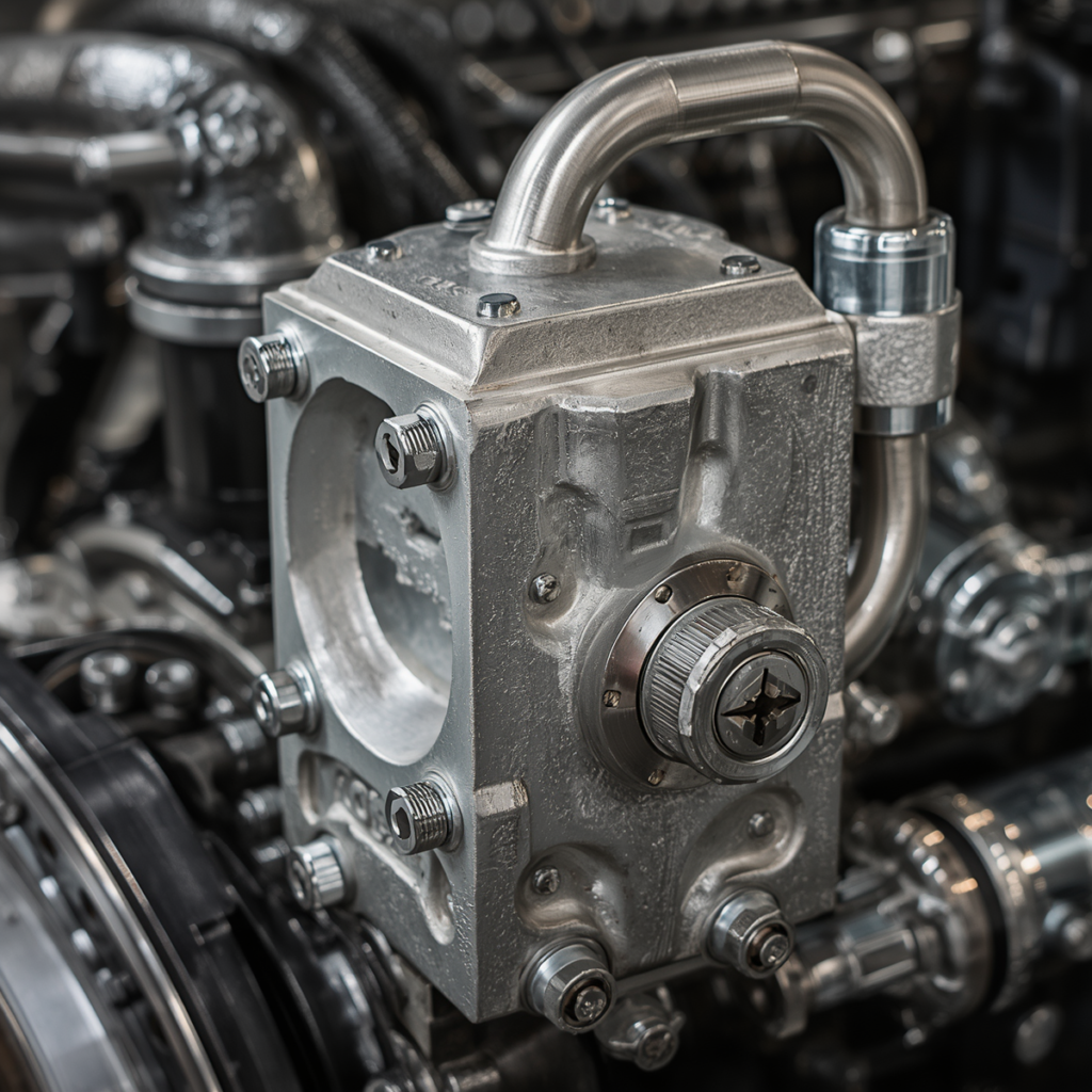
The Fuel Oil Pressure Booster Assembly
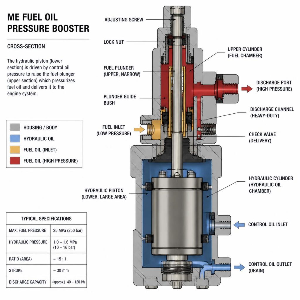
The fuel oil pressure booster, the main muscle of the injection process, sits right on top of the hydraulic manifold block. This vital mechatronic mechanism converts relatively low-pressure hydraulic servo oil to the severe pressures needed to atomise heavy residual fuel oils cleanly. Technical managers use this “Exclusive InsideLook Guide” to master the intricate mechanical forces at work inside this small, high-performance multiplier assembly. This booster design takes the place of the previous mechanical pump plunger so you have complete control over fuel delivery.
Piston and Plunger Alignment
The booster internal core has a large-diameter hydraulic drive piston coupled directly with a significantly narrower high-precision fuel injection plunger. The presented coaxial configuration enables the unit to amplify fluid forces by simple area ratios and without the use of a mechanical cam profile. “Exclusive InsideLook Guide” Technical supervisors looking at this can clearly visualise how this direct physical alignment generates clean, straight-line force transfer. The smooth layout prevents wear from side-thrust to a great extent, hence increasing the operational life of the high-pressure sealing components.
High-Pressure Injection Outlets
The upper part of the booster barrel is equipped with specific discharge apertures, which are connected directly to the fuel valves via short double-walled high pressure pipes. The internal plunger fires upwards and this drives gasoline through these ports at pressures often over 800 bar. Those discharge lines need to be kept short for crisp, sharp injection cutting action and marine engineers who study this “Exclusive InsideLook Guide” understand the importance of that. The tight fit means there is no dribbling of fuel, therefore the crowns of the pistons are protected from severe localised thermal damage.
The Exhaust Valve Actuator Mechanism
In addition to monitoring fuel delivery, the multipurpose HCU block also controls the timing of the main cylinder exhaust cycle. The integrated exhaust valve actuator is located next to the fuel booster and uses the same high pressure hydraulic servo oil supply line. This architecture gives you a “Exclusive InsideLook Guide” to the dual-purpose nature of today’s electro-hydraulic engine control blocks. This close coupling means no long, heavy mechanical pushrods and complicated rocker arm assemblies on top of the cylinders.
Actuator Piston Stroke Dynamics
The actuator consists of a heavy-duty hydraulic piston, which travels upward when high-pressure servo oil is pumped into its lower control chamber. The quick vertical movement causes a certain amount of hydraulic oil to be displaced through a high-pressure line directly to the exhaust valve housing. Maritime sailors using this “Exclusive InsideLook Guide” can simply follow how this hydraulic pushrod replaces the typical mechanical valve lifting gear. This smooth, fluid-driven stroke ensures the huge exhaust valve opens rapidly and seals softly each cycle.
Integrated Hydraulic Dampening Systems
An actuator block contains an interior dampening chamber to protect the large exhaust valve from significant mechanical impact damage during high-speed closing sequences. As the valve nears the seat, the exiting oil is squeezed through a tightening restriction, generating a strong hydraulic cushion . This “Exclusive InsideLook Guide” to Technical Superintendents knows these guys know that this damping effect is crucial to avoid valve face cracking and seat deformation. This fluid cushion extends the service life of pricey exhaust parts for the entire fleet.
The Mechatronic Control Interface
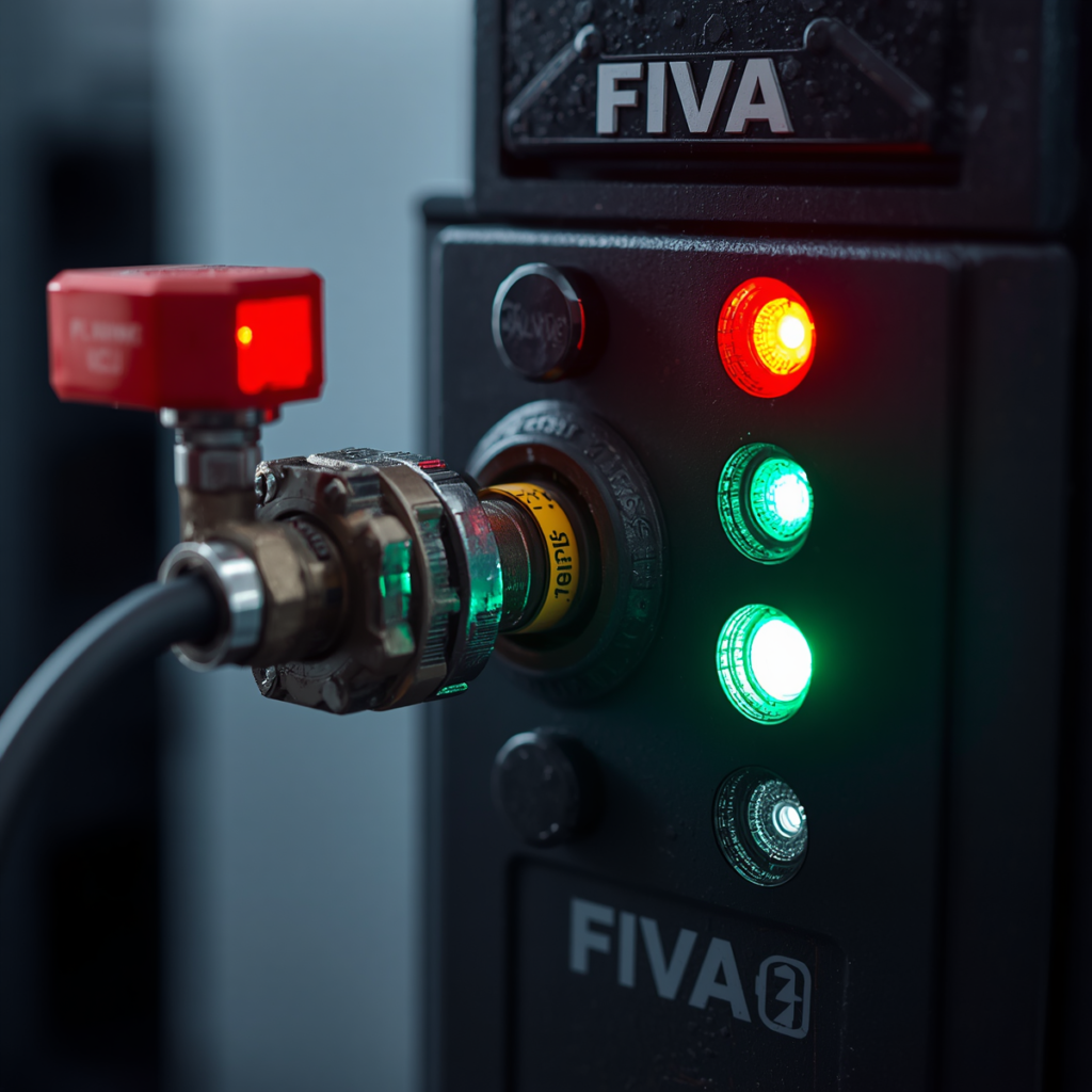
Fast-acting mechatronic proportional valves bolted to the unit control the complex physical motions of the fuel booster and the exhaust valve actuator. These high-precision interfaces are the essential connection between the ship’s digital control software and the brute mechanical force of the hydraulic system. This seamless integration of physical hardware and software directly represents Maritime Digitalization Pathways: Intelligently Automating Large Engines across modern merchant fleets. This section provides an “Exclusive InsideLook Guide” to the quick mechatronic spools that run current marine engine timing cycles. They react in fractions of a millisecond to guarantee that the cylinders are perfectly synchronised.
FIVA and ELFI Mounting Pads
The cast manifold block has machined external mounting surfaces that are specifically intended to support the fast-acting FIVA or ELFI mechatronic valve assemblies. These increasing pads include properly aligned oil port drillings that immediately connect the valve spools to the internal hydraulic supply circuits. Fleet technical managers reading this Exclusive InsideLook Guide will appreciate how this direct-bolted design eliminates the need for vulnerable external control piping lines. This sleek design shields the critical mechatronic interconnections from the strong structural vibrations of the engine.
Sensor Feedback Array Integration
The unit is equipped with a complete set of inductive position and stroke feedback sensors for full control of the injection cycle. These sensitive electronic gadgets continuously measure the precise physical location of the internal booster plungers and valve spools while in operation. This “Exclusive InsideLook Guide” is available to help engineering teams understand how these sensors constitute a very intelligent, closed-loop diagnostic network. This constant stream of data enables the main computer to make instantaneous timing modifications that help optimise combustion.
Nitrogen-Charged Accumulator Blocks
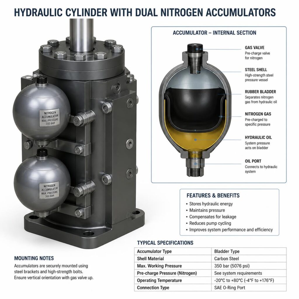
The fuel boosters and exhaust actuators require huge volumes of hydraulic fluid in milliseconds , thus you need localised energy storage . To satisfy this severe fluid requirement, each unit has a set of small, high pressure nitrogen charged accumulators fastened directly to the manifold. The architecture provides a “Exclusive InsideLook Guide” to the crucial shock-absorption and energy-storage mechanisms employed in today’s mechatronic engines. These devices prevent harmful pressure decreases and smooth out disruptive pulsations of the fluid during rapid cycling.
Smoothing Pressure Pulsations
An enormous volume of hydraulic oil is required for a fuel booster firing, and it is delivered instantaneously, which can generate violent, destructive pressure waves in the supply pipework. This is solved by the localised accumulators, which rapidly dump the collected fluid energy, essentially killing these sharp hydraulic shocks before they can go into the main lines. Consulting engineers using this “Exclusive InsideLook Guide ” understand that stopping these pressure ripples is important to avoid pipe welds from splitting due to fatigue. This damping effect provides a constant uniform hydraulic supply pressure to all units.
Stored Energy for Rapid Cycling
Inside each accumulator tank there is a flexible bladder which is pre-charged with pure nitrogen gas compressed to a very stringent pressure level depending on the load. This compressed gas acts like a powerful mechanical spring, pressing back on the hydraulic oil to give an instant reserve of fluid power. Technical superintendents who have this ‘Exclusive InsideLook Guide’ know that the gas charge should be checked often to ensure the valves are functioning properly. The localised energy storage lets the engine ramp up quickly without having to call on the main hydraulic pump station.
Internal Lubrication and Drainage Networks
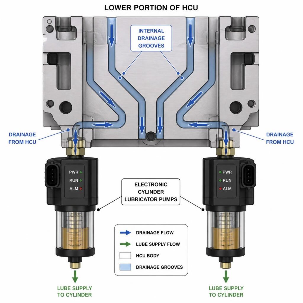
These specialised electronic Alpha Lubricator modules are sometimes mounted directly on the lower structural base plates of modern electronic units, and are therefore under the same servo oil pressure. This tiny arrangement allows the engine computer to spray lubricating oil for the cylinders on the liner surfaces at the exact microsecond the piston rings pass the injection quills. Chief engineers using this “Exclusive InsideLook Guide” may discover how this integrated design optimises liner protection and reduces lubricating oil consumption. This exact delivery prevents cylinder liner scuffing and cuts down on total maintenance expenses.
Integrated Alpha Lubricator Blocks
These specialised electronic Alpha Lubricator modules are sometimes mounted directly on the lower structural base plates of modern electronic units, and are therefore under the same servo oil pressure. This tiny arrangement allows the engine computer to spray lubricating oil for the cylinders on the liner surfaces at the exact microsecond the piston rings pass the injection quills. Chief engineers using this “Exclusive InsideLook Guide” may discover how this integrated design optimises liner protection and reduces lubricating oil consumption. This exact delivery prevents cylinder liner scuffing and cuts down on total maintenance expenses.
Safe Drain and Leakage Channels
The manifold also has separate drainage channels to capture any fuel oil or hydraulic fluid that leaks beyond the internal seals, to safeguard the main engine system. The lines dump the leakage to a central monitoring tank with automatic high level float alarms to advise the crew of seal wear. Those in the marine profession who study this “Exclusive InsideLook Guide” know that separating these leakage channels is critical to avoiding contamination of the clean servo oil loop by heavy fuel. This drainage safety framework ensures that the essential hydraulic system runs smoothly.
Diagnostic Testing and Calibration Protocols
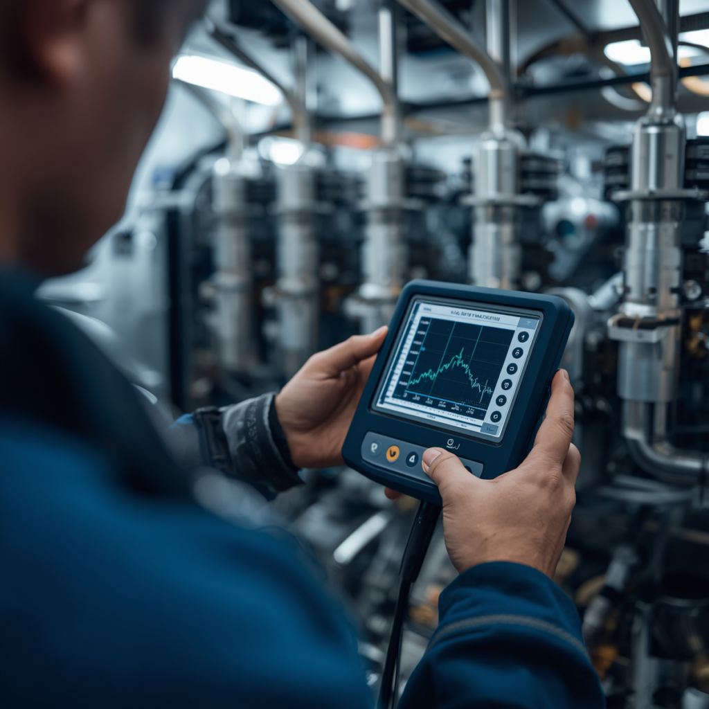
We have a systematic approach to perform diagnostic testing and software calibration of the hydraulic manifold to ensure structural integrity and operational efficiency. Over extended ocean passages, large cycle pressure fluctuations can create tiny mechanical timing shifts that have to be corrected immediately in the primary engine control computers. This “Exclusive InsideLook Guide” gives technical management teams access to the exacting calibration methods through the main operating panel interface, assuring they can execute them. Such proactive diagnostic procedures allow shipboard engineers to validate mechatronic responsiveness, calibrate internal sensors and ensure consistent power balancing of all operational engine cylinders.
FIVA Stroke Optimization Checks
A significant element of the regular maintenance schedule is to check the quick movement and stroke profile of the proportional mechatronic valve spools. Engineers conduct automated diagnostic programs that command the spool through its whole travel range and observe the inductive position sensors for latency. An “Exclusive InsideLook Guide” of these stroke test logs shows early evidence of varnish development or mechanical stickiness from minuscule oil impurities. Keeping these spools in precise calibration saves the engine from abrupt injection delays and provides highly predictable fuel booster operation.
Pressure Transducer Calibration Methods
The electronic control computer is fully dependent on pressure data coming from electronic transducers installed directly into the high pressure hydraulic supply channels. If a transducer begins to wander out of calibration, the computer will get false pressure readings and will send the wrong timing orders to the cylinders, and their performance will suffer. Using these very same calibration processes provides a critical “Exclusive InsideLook Guide” on how to perform correct manual cross-checks with certified master mechanical pressure gauges. Regular sensor alignment helps to keep system control loops tight, safeguarding the entire machinery block from harmful, unexpected pressure spikes.
Conclusion

Demystifying the complex physical design of the Hydraulic Cylinder Unit uncovers the astounding engineering advances that characterise modern commercial marine propulsion units. Integration of the fuel booster, exhaust valve actuator, mechatronic interfaces and localised accumulators into a single modular block, brings improved flexibility and safety to today’s engines. This tiny per-cylinder configuration totally eliminates previous mechanical failure spots and opens the door to fully digital management of the combustion cycle. This mastery of physical details is the key “Exclusive InsideLook Guide” needed to successfully operate, troubleshoot and maintain modern automated vessel propulsion systems across the globe-wide fleet.
People Also Ask
Why is the Hydraulic Cylinder Unit framework physically split into independent blocks for each cylinder instead of using a single centralized manifold?
The system is subdivided , such that a failure of one component will not shutdown the whole engine . This Exclusive InsideLook Guide arrangement isolates individual cylinders in an emergency.
What operational indicators alert a shipboard engineering crew that an HCU accumulator has lost its nitrogen gas pre-charge pressure?
Engineers see this with strong high pressure pipe vibrations and timing warnings on the MOP. This “Exclusive InsideLook Guide” tip helps to pinpoint bladder failures quickly.
How does the integrated internal drainage channel network inside the block prevent heavy fuel oil from contaminating the clean hydraulic servo oil loop?
Specialised collection grooves capture plunger leakage and direct it to a monitoring tank. This “Exclusive InsideLook Guide” design prevents gasoline from mixing into clean servo oil.
What specific mechanical advantages are gained by mounting the mechatronic FIVA valves directly onto the machined face of the HCU block manifold?
Direct attachment eliminates vulnerable external pipes altogether and decreases hydraulic lag. This “Exclusive InsideLook Guide” detail assures the highest mechatronic timing precision.